Tag Archives: flexible shaft price

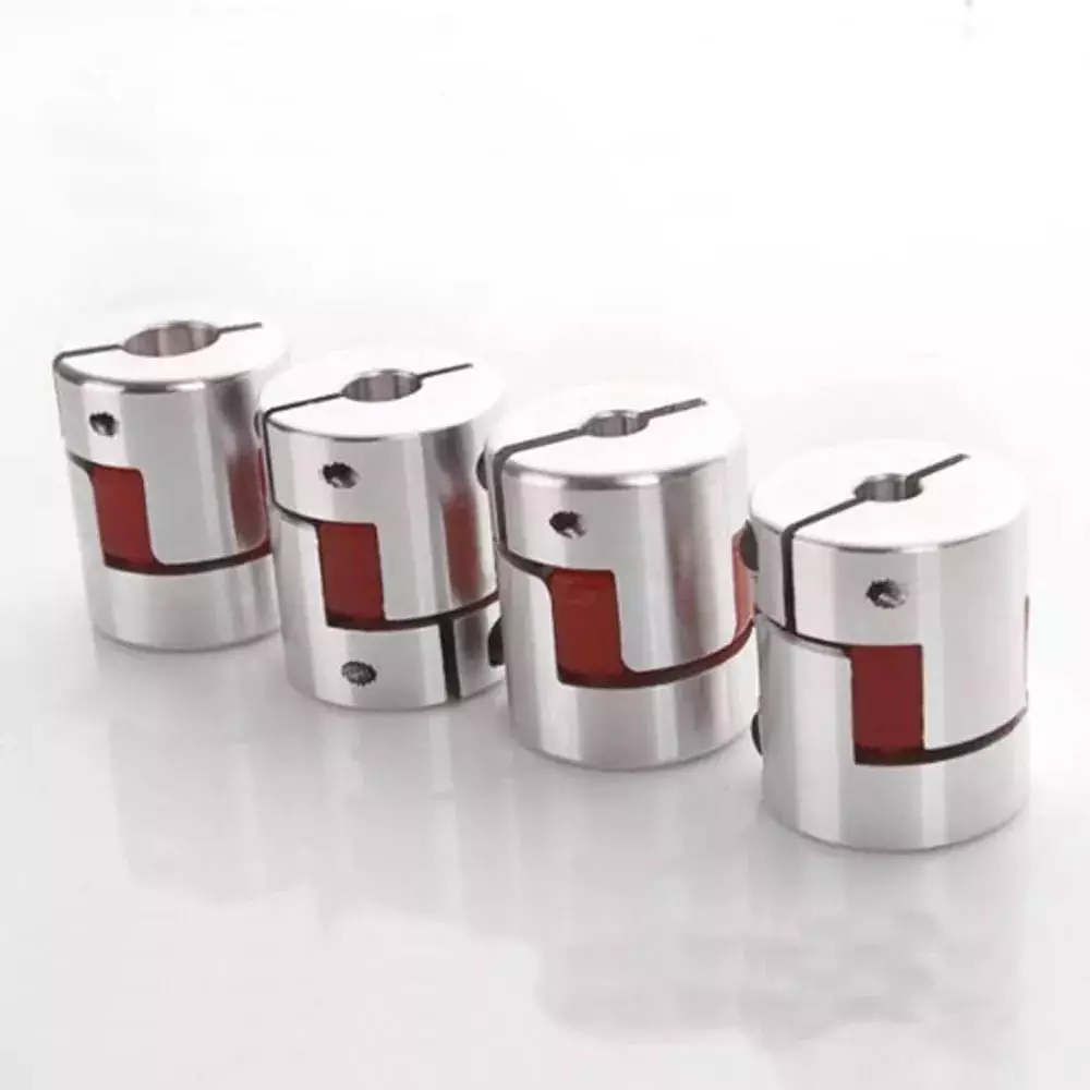
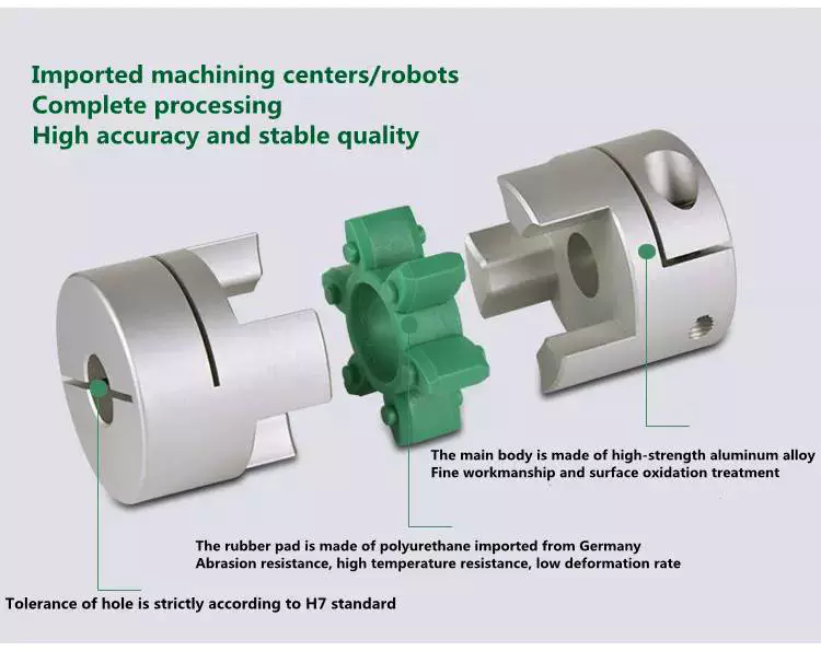
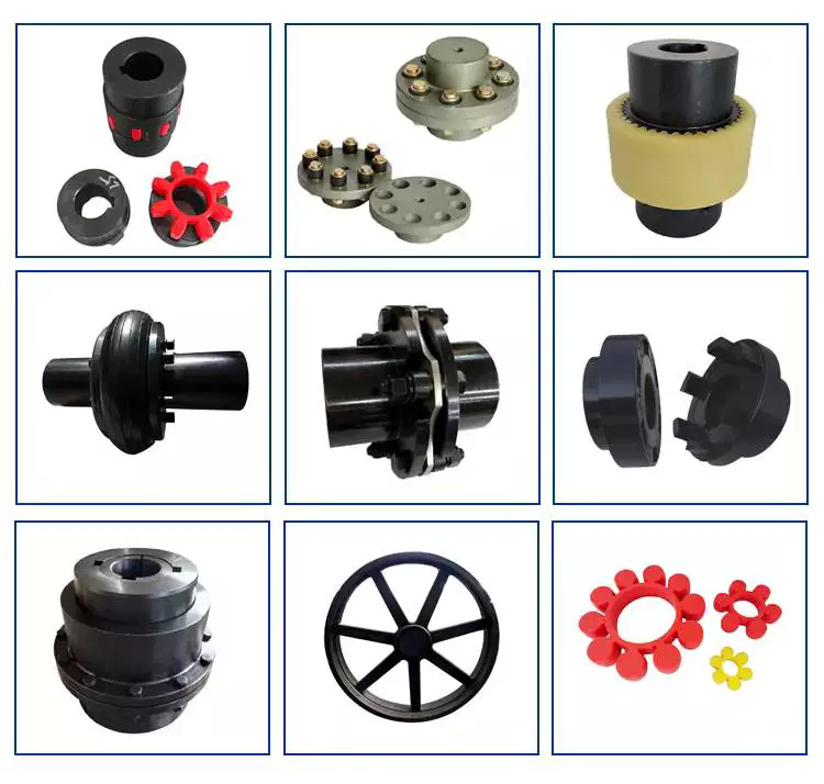
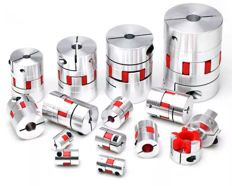
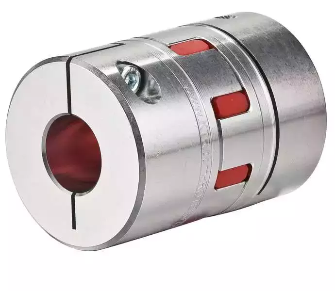
China Coupling Manufacturer Keyway type disc coupling Factory Price 45# steel high torque stepmotor connect flexible shaft coupling coupling connector

Guarantee: 1 years
Relevant Industries: Garment Outlets, Creating Materials Outlets, Manufacturing Plant, Equipment Restore Stores, Food & Beverage Manufacturing facility, Coupling Maker keyless shaft hub locking device cam assembly electrical power lock adjustable protected locking gadget Farms, Vitality & Mining, Other
Custom-made assist: OEM
Structure: Disc
Versatile or Rigid: Flexible
Standard or Nonstandard: Common
Material: Metal
Solution name: Keyway kind disc coupling
Type: TS3K
Application: Industrial Gear
Entire body Material: forty five# metal
Size: Regular Measurement
Coloration: Black
Floor Treatment: Blackening
Certification: ISO9001:2015
MOQ: 1 Established
High quality: a hundred%tested
Packaging Specifics: standard export packing and wooden pallets packing
Port: ZheJiang port, China

Very hot Sale

1. Product Identify Keyway Kind disc coupling
2. Kind TS3K
3. ApplicationShaft Relationship
four. ManufacturerHangZhou CZPT
five. MOQone Established
six. ValueEXW price tag
7. Shipping WayBy sea, DHL, Coupling company JQ-fifty clamping coupling 45# metal for motor link Factory Price tag rigid shaft coupling sizzling sale UPS, Fedex or as customers’ specifications
8. Payment TermsBy means of T/T
nine. Shipping and delivery TimeWithin fifteen-twenty workdays following deposit or as customers’ need
ten. Packaging1. Export Picket Box
two. Carton Box
3. We can perform according to customers’ requirements
Contact us
Certifications
Firm Details
Packaging & Coupling Manufacturer grid coupling JS6 snake spring shaft link torque transmission Factory Price higher top quality Shipping and delivery
Programs
FAQ

What Is a Coupling?

A coupling is a device that connects two shafts together. It transmits power from one to the other and is used to join rotating equipment. It can also allow for some degree of misalignment and end movement. It is used in mechanical engineering and manufacturing. To learn more about couplings, read this article.
gearboxMechanical connection between two objectsThe present invention relates to a method and assembly for forming a mechanical connection between two objects. The methods of this invention are suitable for connecting both solid and hollow objects. For example, the method can be used to make mechanical connections between two cylinders. This method is particularly useful for connecting two cylinders that are positioned near each other.

Absorbs vibration

A coupling insert is a part of a vehicle’s drivetrain that absorbs vibrations. These inserts are designed to prevent couplings from moving out of phase. However, the coupling inserts themselves can wear out and need to be replaced. Universal joints are an alternative if the coupling is out of phase by more than one degree. In addition, internal bearings in the coupling need to be lubricated and replaced when they begin to show signs of wear.
Another embodiment of the invention includes a flexible coupling 25 that includes rearwardly-extending lugs that extend toward the coupling member 23. These lugs interdigitate with corresponding lugs on the coupling member 23. They are spaced circumferentially. A first elastic member 28 is interposed between lugs 26 and 27, and is adapted to yield in a counterclockwise direction. As a result, it absorbs torsional vibrations.
gearbox

Blocks heat transfer

Thermal coupling occurs when a solid block is thermally coupled to the air or fluid passing through it. The amount of heat transferred through a solid block depends on the heat transfer coefficients of the materials. This paper presents a numerical model to understand how heat transfers through different block materials. This work also describes the thermal resistance network for a one-dimensional block.
In some cases, thermal coupling increases the heat transfer mechanism. As illustrated in FIG. 1D, a heatpipe coupler 112 couples two heatpipes 110-1 and 110-2. This configuration allows the pipes to be coupled to the heat source and to the condenser. In addition, the heat pipe couplers may have bellows at the ends to help facilitate linear motion.
Thermal coupling is achieved by ensuring that at least one block is made of a material with a lower thermal expansion coefficient than the annulus. Ideally, the block’s mean thermal expansion coefficient is at least twenty percent lower than the annulus’s mean thermal expansion coefficient. This ensures that the thermal coupling between the two parts is as efficient as possible.
Another type of thermal coupling is achieved by using flexible elements. These are often washers or springs. These components allow the blocks to maintain physical contact with the post 55, which means that the heat transfer is more efficient even at higher temperatures. The flexibility of these elements also makes it possible to choose an element that will not impede assembly.
gearbox

Protects rotating equipment

A reliable, long-lasting coupling system can reduce the risk of damage to rotating equipment. Designed to protect against torque overload and wear, Voith torque-limiting couplings provide outstanding safety and reliability. As a result, they can deliver maximum performance and minimize equipment downtime. In addition to their long-term benefits, these solutions are ideal for applications where safety and reliability are of paramount importance.
A good coupling provides many advantages, including the ability to transmit power, compensate for axial movement, and absorb shock. It is essential to choose the proper coupling for your application based on the basic conditions of your rotating equipment. For example, if you have two shafts with parallel rotation axes, you should choose a parallel coupling. Otherwise, you should use an angular coupling.
Torque-limiting couplings can also provide protection for rotating equipment by disengaging at a specific torque level. This protects the drive shaft from undergoing catastrophic failure. Torque limiters are particularly helpful for high-value equipment. By preventing catastrophic failure, you can avoid expensive repairs and minimize equipment downtime.
Coupling guards are easy to install and provide effective protection for rotating equipment. These covers are made of sheet metal bent to fit over the shaft. They are durable and easy to remove when necessary. This type of guard can prevent employees from catching their hands, tools, or loose clothing on motor coupling components.
China Coupling Manufacturer Keyway type disc coupling Factory Price 45# steel high torque stepmotor connect flexible shaft coupling     coupling connectorChina Coupling Manufacturer Keyway type disc coupling Factory Price 45# steel high torque stepmotor connect flexible shaft coupling     coupling connector
editor by czh 2023-03-17

China Cheap price CALT 6mm bore flexible shaft coupling similar E69-CO6B coupling alignment

Structure: Common
Flexible or Rigid: Versatile
Common or Nonstandard: Common
Materials: Plastic/glass fibers
Design Number: CF15-6-6
Type: Flexible Coupling
Customize: Settle for Unique Personalize
Size: 20 mm
Bore Dimensions: Each are 6mm
Outer dia: 15mm
Packaging Particulars: Standard Sturdy Export Carton Box

Low cost price tag CALT 6mm bore flexible shaft coupling comparable E69-CO6B Other Coupling.For we are company, and we are CZPT to take your customize. You should verify the image bellowing and e mail us the product you require, we will ship the datasheet to you shortly.
Connected ProductsSolid shaft kind GHS38 Series.Widely employed in automatic management, automatic measurement, as the angle and pace sensors.

ASIC gadgets inner, great dependability, extended daily life, anti-jamming performance. Stainless steel shaft has a increased stability and protection.Metal shell is far more reliable and anti-impact. Bearing load weighty, anti-oil and water
Servo-motor Encoder GSM48 Collection.Widely utilized in the area of automatic management AC servo unit, specifically ideal for use in servo motor supporting.

Internal ASIC devices, substantial dependability, prolonged existence, sturdy anti-interference. Wide variety of resolutions, and does not need signal conditioning. With A, B, Z and U, V, W 6-channel signal output can be connected with common line driver (26LS31) RS422, Very good top quality Farm machinery components GEARBOX OIL FILTER W9501-35000 HH3A0-82630 for CZPT Tractor Combine Harvester Spareparts can give twelve output sign, and is suitable with TTL
Hollow Shaft Kind GHH100 sequence.Utilised in automatic handle, measurement, robot X-Y operating system, printing and packaging.
Interior ASIC products, large dependability, lengthy daily life, powerful anti-interference. a lot more solid metal housing could anti-shock. Outlet conclude steel interface sets of waterproof security.
Draw-wire Position Sensor CESI series.compact dimensions, rugged design, effortless to set up
economic price, and value cost savings for customersVarious alerts output optional: thrust-pull, TTL, open collector and so on
The cylinders, screening equipment and other market has reached massive-scale applications, reliability
Handbook Pulse Generator TM1469 series.For CNC equipment origin correction and signal split.

Total plastic housing, substantial dielectric power, the axis transfer swap and Oil Air pollution Avoidance seal layout.
Our CompanyZheJiang Qiyi Electrical & Mechanical Gear Co., Tiny gears Wholesale OEM Manufacturing facility Common and customized High Precision Spur pinion Gear Ltd. has specialized in encoder, sensor, motor and related merchandise for numerous several years, found in Chinese company and port center, ZheJiang . CALT brand merchandise ranges: Optical incremental rotary encoder, one-turn and multi-change absolute encoder, attract-wire position sensor and couplings, and other devices, which broadly employed in CNC equipment, textile equipment, metal rolling equipment, linear CZPT program, hydraulic technique, lifting machinery and servo motor, all get a extremely excellent track record! Qiyi organization has received unbiased import and export qualification in 2013, CALT model items have been exported to Southeast Asia, Europe, China Manufacturers Large Precision Cnc Milling Turning Support Metal Bevel Gears Personalized Gears Spur Plastic Gears Sets The us and Russia and other countries and regions in the globe.
Our Factory Packing & Delivery 1. Rotary encoder pack box 2 layers.2. All packed excellentthree. Encoder module disc in plastic box four. Ziplock packed for versatile coupling five. Rotary encoder packed properlysix. Packed with great circumstances with transport mark.FAQ Get in touch with

Types of Couplings

A coupling is a device that connects two shafts and transmits power from one to the other. Its main purpose is to join two pieces of rotating equipment. It also allows for some degree of misalignment or end movement. Here are a few examples of coupling types: Beam coupling, Flexible coupling, Magnetic coupling, and Shaft coupling.
gearbox

Beam coupling

Beam couplings are used to couple motors and other devices. They are available in several types, including flexible, slit, and rigid beam couplings. Each has unique properties and characteristics. These couplings are best for applications requiring a high level of precision and long life. They are also a practical solution for the connection of stepping and servo motors with screw rods.
Beam couplings are usually made of stainless steel or aluminum alloy, and feature spiral and parallel cut designs. Multiple cuts allow the coupling to accommodate multiple beams and improve angular and parallel misalignment tolerances. Additionally, beam couplings are comparatively cheaper than other types of rotary joints, and they require minimal maintenance.
The materials of a beam coupling should be considered early in the specification process. They are typically made of aluminum or stainless steel, but they can also be manufactured from Delrin, titanium, and other engineering grade materials. Beam couplings are often available in multiple sizes to fit specific shaft diameters.
Beam couplings are a key component of motion control systems. They provide excellent characteristics when used properly, and they are a popular choice for many applications. A thorough understanding of each type of coupling will help to prevent coupling failure and enhance system performance. Therefore, it is important to choose the right coupling for your application.
Various types of beam couplings have unique advantages and disadvantages. The FCR/FSR design has two sets of three beams. It is available in both metric and inch shaft sizes. The FCR/FSR couplings are ideal for light-duty power transmission applications. A metric shaft is more suitable for these applications, while an inch shaft is preferred for heavier duty applications.
Two types of beam couplings are available from Ruland. The Ruland Flexible beam coupling has a multi-helical cut design that offers a greater flexibility than commodity beam couplings. This design allows for higher torque capabilities while minimizing wind-up. In addition, it is also more durable than its commodity counterparts.

Flexible coupling

A flexible coupling is a versatile mechanical connection that allows for the easy coupling of two moving parts. The design of these couplings allows for a variety of stiffness levels and can address a variety of problems, such as torsional vibrations or critical speed. However, there are a number of tradeoffs associated with flexible couplings.
One of the biggest issues is the installation of the coupling, which requires stretching. This problem can be exacerbated by cold temperatures. In such a case, it is vital to install the coupling properly. Using a gear clamp is one of the most important steps in a successful installation. A gear clamp will keep the coupling in place and prevent it from leaking.
Another common type of flexible coupling is the gear coupling. These couplings are composed of two hubs with crowned external gear teeth that mesh with two internally splined flanged sleeves. The massive size of the teeth makes them resemble gears. Gear couplings offer good torque characteristics but require periodic lubrication. These couplings can also be expensive and have a limited number of applications.
Another type of flexible coupling is the SDP/SI helical coupling. These couplings can accommodate axial motion, angular misalignment, and parallel offset. This design incorporates a spiral pattern that makes them flexible. These couplings are available in stainless steel and aluminum.
A flexible coupling has a wide range of applications. Generally, it is used to connect two rotating pieces of equipment. Depending on its design, it can be used to join two pieces of machinery that move in different directions. This type of coupling is a type of elastomeric coupling, which has elastic properties.
There are many types of flexible couplings available for different types of applications. The purpose of a flexible coupling is to transmit rotational power from one shaft to another. It is also useful for transmitting torque. However, it is important to note that not all flexible couplings are created equally. Make sure to use a reputable brand for your coupling needs. It will ensure a reliable connection.
The simplest and most commonly used type of flexible coupling is the grid coupling. This type of coupling uses two hubs with slotted surfaces. The steel grid is allowed to slide along these slots, which gives it the ability to flex. The only limitation of this type of coupling is that it can only tolerate a 1/3 degree misalignment. It can transmit torques up to 3,656 Nm.
gearbox

Magnetic coupling

Magnetic coupling is a technique used to transfer torque from one shaft to another using a magnetic field. It is the most common type of coupling used in machinery. It is highly effective when transferring torque from a rotating motor to a rotating shaft. Magnetic couplings can handle high torques and high speeds.
Magnetic coupling is described by the energy difference between a high-spin state and a broken symmetry state, with the former being the energy of a true singlet state. In single-determinant theories, this energy difference is called the Kij. Usually, the broken-symmetry state is a state with two interacting local high-spin centers.
The magnetic coupling device is regarded as a qualitative leap in the reaction still industry. It has solved a number of problems that had plagued the industry, including flammability, explosiveness, and leakage. Magnetic couplings are a great solution for many applications. The chemical and pharmaceutical industries use them for various processes, including reaction stills.
Magnetic couplings are a good choice for harsh environments and for tight spaces. Their enclosed design keeps them fluid and dust-proof. They are also corrosion-resistant. In addition, magnetic couplings are more affordable than mechanical couplings, especially in areas where access is restricted. They are also popular for testing and temporary installations.
Another use for magnetic coupling is in touch screens. While touch screens use capacitive and resistive elements, magnetic coupling has found a cool new application in wireless charging. While the finger tracking on touch screens may seem like a boley job, the process is very sensitive. The devices that use wireless charging need to have very large coils that are locked into resonant magnetic coupling.
Magnetic couplings also help reduce hydraulic horsepower. They cushion starts and reduce alignment problems. They can also improve flow in oversized pumps. A magnetic coupling with an 8 percent air gap can reduce hydraulic HP by approximately 27 percent. In addition, they can be used in aggressive environments. They also help reduce repair costs.
Magnetic couplings are a great choice for pumps and propeller systems because they have the added advantage of being watertight and preventing shaft failure. These systems also have the benefit of not requiring rotating seals.
gearbox

Shaft coupling

A shaft coupling joins two shafts and transmits rotational motion. Generally, shaft couplings allow for some degree of misalignment, but there are also torque limiters. Selecting the right coupling can save you time and money and prevent equipment downtime. Here are the main features to consider when purchasing a coupling for your application.
Shaft couplings should be easy to install and disassemble, transmit full power to the mated shaft, and reduce shock loads. A shaft coupling that does not have projecting parts should be used for machines that move or rotate at high speeds. Some types of shaft couplings are flexible while others are rigid.
Shaft couplings can be used in a variety of applications, including piping systems. They can be used to connect shafts that are misaligned and help maintain alignment. They can also be used for vibration dampening. Shaft couplings also allow shafts to be disconnected when necessary.
Shaft couplings can accommodate a certain amount of backlash, but this backlash must be well within the tolerance set by the system. Extremely high backlash can break the coupling and cause excessive wear and stress. In addition, excessive backlash can lead to erratic alignment readings. To avoid these issues, operators must reduce backlash to less than 2deg.
Shaft couplings are often referred to by different names. Some are referred to as “sliced” couplings while others are known as “slit” couplings. Both types offer high torque and torsional stiffness. These couplings are typically made from metals with various alloys, such as acetal, stainless steel, or titanium.
CZPT Pulley produces shaft couplings for a variety of applications. These products are used in high-power transmission systems. They have several advantages over friction couplings. In addition to minimizing wear, they don’t require lubrication. They are also capable of transmitting high torque and high speeds.
Another type of shaft coupling is the universal coupling. It is used to transmit power to multiple machines with different spindles. Its keyed receiving side and flanges allow it to transmit power from one machine to another.
China Cheap price CALT 6mm bore flexible shaft coupling similar E69-CO6B     coupling alignmentChina Cheap price CALT 6mm bore flexible shaft coupling similar E69-CO6B     coupling alignment
editor by czh 2023-02-22

China BB Snake Spring Clamping 6mm 8mm 10mm Shaft Encoder Motor Flexible Coupling Pipe Joint Couplings Coupler/Economic Price (IBEST) coupling bushing

Relevant Industries: Manufacturing Plant, Machinery Fix Outlets, Foods & Beverage Manufacturing facility, Energy & Mining
Structure: Universal
Versatile or Rigid: Flexible
Common or Nonstandard: Regular
Materials: Aluminium Alloy, Stainless metal spring + Metallic screws
Coupling Sort: Flexible
Shaft dimension: 6mm or 8mm or 10mm or 12mm (other Specified)
Outer diameter: 22-23mm
Size: 32mm
Torque: 4-12 N
Special need: Shaft dimension of every end can be various and specifically ordered
Packaging Particulars: 1pc/poly bag

IBEST BB Snake Spring Kind Adaptable coupling

Features:
* Standard: Exterior D=22-23mm, duration=32mm. (Other Outside the house D and length, make sure you refer to below datasheet)* Diameter of hollow shaft : Standard hole 4mm, 5mm, 6mm, 6.35mm, 8mm, 10mm or 12mm. ( Bigger hole dimension, need to have to be specified when purchasing)
* With stainless steel spring + Aluminum, with 2 screws for clamping.
* Human body material:Tough Alumium alloy, Sleeve substance:Stainless metal bellows.
* Zero backlash. * Superb reaction and substantial torque capability. * Similar clockwise and anti-clockwise rotational qualities.
* BB sequence coupling use setscrews to hold the axis.lt is handy to assemble and disassemble.and no hurt will be brought on to the shaft.* BB sequence versatile coupling can be usde for minor torque &place. Specification on request.(Special bore dimension and slot available on request)* lnstructions BB collection be part of with locking assembly.zero backlash.convenient to assemble and disassemble.
* For servomotor, stage motor link.

elcome to speak to us!
IBEST ELECTRICAL CO.LTD
wwwibestchinacom

What Is a Coupling?

A coupling is a mechanical device that links two shafts together and transmits power. Its purpose is to join rotating equipment while permitting a small amount of misalignment or end movement. Couplings come in a variety of different types and are used in a variety of applications. They can be used in hydraulics, pneumatics, and many other industries.
gearbox

Types

Coupling is a term used to describe a relationship between different modules. When a module depends on another, it can have different types of coupling. Common coupling occurs when modules share certain overall constraints. When this type of coupling occurs, any changes to the common constraint will also affect the other modules. Common coupling has its advantages and disadvantages. It is difficult to maintain and provides less control over the modules than other types of coupling.
There are many types of coupling, including meshing tooth couplings, pin and bush couplings, and spline couplings. It is important to choose the right coupling type for your specific application to get maximum uptime and long-term reliability. Listed below are the differences between these coupling types.
Rigid couplings have no flexibility, and require good alignment of the shafts and support bearings. They are often used in applications where high torque is required, such as in push-pull machines. These couplings are also useful in applications where the shafts are firmly attached to one another.
Another type of coupling is the split muff coupling. This type is made of cast iron and has two threaded holes. The coupling halves are attached with bolts or studs.
gearbox

Applications

The coupling function is an incredibly versatile mathematical tool that can be used in many different scientific domains. These applications range from physics and mathematics to biology, chemistry, cardio-respiratory physiology, climate science, and electrical engineering. The coupling function can also help to predict the transition from one state to another, as well as describing the functional contributions of subsystems in the system. In some cases, it can even be used to reveal the mechanisms that underlie the functionality of interactions.
The coupling selection process begins with considering the intended use of the coupling. The application parameters must be determined, as well as the operating conditions. For example, if the coupling is required to be used for power transmission, the design engineer should consider how easily the coupling can be installed and serviced. This step is vital because improper installation can result in a more severe misalignment than is specified. Additionally, the coupling must be inspected regularly to ensure that the design parameters remain consistent and that no detrimental factors develop.
Choosing the right coupling for your application is an important process, but it need not be difficult. To find the right coupling, you must consider the type of machine and environment, as well as the torque, rpm, and inertia of the system. By answering these questions, you will be able to select the best coupling for your specific application.
gearbox

Problems

A coupling is a device that connects two rotating shafts to transfer torque and rotary motion. To achieve optimal performance, a coupling must be designed for the application requirements it serves. These requirements include service, environmental, and use parameters. Otherwise, it can prematurely fail, causing inconvenience and financial loss.
In order to prevent premature failure, couplings should be properly installed and maintained. A good practice is to refer to the specifications provided by the manufacturer. Moreover, it is important to perform periodic tests to evaluate the effectiveness of the coupling. The testing of couplings should be performed by qualified personnel.
China BB Snake Spring Clamping 6mm 8mm 10mm Shaft Encoder Motor Flexible Coupling Pipe Joint Couplings Coupler/Economic Price (IBEST)     coupling bushingChina BB Snake Spring Clamping 6mm 8mm 10mm Shaft Encoder Motor Flexible Coupling Pipe Joint Couplings Coupler/Economic Price (IBEST)     coupling bushing
editor by czh

China Lower Price Motor Shaft Coupler/ Flexible Helical Beam Coupling/coupler coupling and repulsion

Guarantee: 3 several years
Applicable Industries: Hotels, Garment Shops, Constructing Material Outlets, Producing Plant, Machinery Restore Stores, Foods & Beverage Manufacturing unit, Farms, Cafe, House Use, Retail, Food Store, Printing Outlets, Building works , Strength & Mining, Meals & Beverage Stores, Advertising Business
Personalized assistance: OEM, ODM, OBM
Framework: Jaw / Spider
Flexible or Rigid: Flexible
Regular or Nonstandard: Normal
Substance: Aluminium
Product title: versatile couplings coupler
Application: Cnc Equipment 3d Printer
Physique Content: Stainless Steel Aluminum Metal
ball materials: chrome steel ball ,stainless steel, nylon ball
Spider colour: Purple (Environmentally friendly and Yellow selected)
Size: Custom made made
Bore diameter: As customized demands
Mounted sort: Encoder Versatile Coupling
Certification: ISO9001:2008
samples: accessible
Packaging Particulars: Neutual packing, shade box, polybag, tube packing,carton box etc.

Reduced Price Motor Shaft Coupler/ Flexible Helical Beam Coupling/coupler

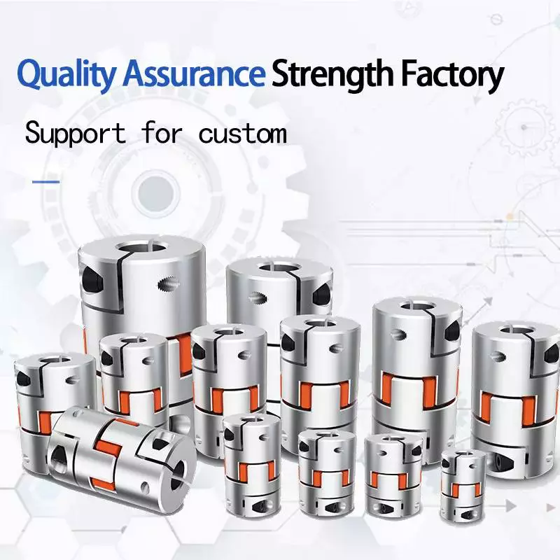
Adaptable shaft jaw coupling spider coupler for CNC transmission device stepper servo motor
one. Device from a Aluminum rod, for a lot more steady performance
2. High concentricity enable equipment correct managing
three. Very good ending for exact matching
four. Clamp or set screw each for alternative
five. Various measurement for 2 hubs is obtainable (d1 & d2 can be distinct measurement)

Standard info as below can be refered to
Outside diameterLengthInside of diameter
twenty mm34 mm5/6/7/10 mm
25 mm34 mmsix/6.35/7/8/9/ten/twelve mm
30 mmforty two mmsix/8/10/11/twelve/14/fifteen/16 mm
forty mm66 mmten/11/twelve/14/15/sixteen/17/18/19/20/22 mm
fifty five mmseventy eight mmfourteen/fifteen/sixteen/18/19/twenty/22/24/twenty five/28/thirty mm
65 mmninety mm16/18/19/20/22/24/25/28 mm
eighty mm114 mm20/25/28/230/32 mm
Can be custom-made in accordance to customers’ demands about aperture dimension and duration
High-quality resources and CNC for precision promise for our customers
Feature

  • Lightweight aluminum variation of the sector regular shaft coupling
  • Interchangeable with L and SS line of hubs
  • Corrosion resistant (finished bores passivated for added safety)
  • Accommodates for angular and parallel shaft misalignment
  • Fall short-risk-free – will even now execute if elastomer “spider” fails
  • No steel to metallic contact
  • Resistant to oil, dust, sand, humidity, and grease

  • Model
    Inner bore
    D
    (mm)
    L
    (mm)
    Nominal Torque
    (N.m)
    The Max of Torque
    (N.m)
    dmin
    dmax
    JM2-25
    4
    12
    25
    34
    five.
    ten.
    JM2-30
    6
    sixteen
    thirty
    35
    seven.four
    fourteen.8
    JM2-forty
    10
    24
    forty
    sixty six
    nine.5
    19.
    JM2-55
    12
    28
    55
    seventy eight
    34
    sixty eight
    JM2-sixty five
    fourteen
    38
    sixty five
    ninety
    95
    one hundred ninety
    JM2-80
    24
    forty five
    eighty
    114
    one hundred thirty five
    270
    JM2-ninety five
    30
    fifty five
    ninety five
    126
    230
    460
    JM2-a hundred and five
    35
    sixty
    one hundred and five
    a hundred and forty
    380
    760
    Design
    Allowable pace
    (rpm)
    Radial Misalignment(m.m)
    Angular
    Misalignment(°)
    Axle
    Misalignment(mm)
    JM2-twenty five
    17000
    0.02
    one.
    +.sixty
    JM2-30
    12000
    0.02
    one.
    +.60
    JM2-40
    10000
    0.02
    1.
    +.80
    JM2-fifty five
    8000
    0.02
    one.
    +.80
    JM2-sixty five
    6000
    0.02
    one.
    +.eighty
    JM2-eighty
    4600
    0.02
    one.
    +1.00
    JM2-ninety five
    3800
    0.02
    one.
    +1.00
    JM2-one hundred and five
    3400
    0.02
    1.
    5mm 8mm versatile coupling 5*8mm cnc Motor jaw shaft coupler

    substantial good quality stepper motor axis shaft flexible couplings

    JM55 D55 ID8*28 L78mm adaptable couplings for stepper motor cnc elements

    Minimal cost 3D printer elements versatile helical shaft coupling

    CNC stepper motor shaft coupling coupler adaptable couplings 8*8mm D25L30

    3D printer 5*5 5*8mm aluminium versatile couplings for stepper motor

    Our ServicesOEM and Custom-made Package deal is Attainable
    Packaging & ShippingNatural package deal:
    White box,Plastic Tubes,Wood cartonsCustomized Bundle In accordance to our customer’s needs
    Shipping and delivery time:3-5 times or according to our customer’s get quantity

    Organization InformationShuangCheng Bearing Co., Ltd. Specializing in various kinds of bearings such as Deep Groove Ball Bearing,608 Skate baring,Taper roller bearing,Cylindrical roller bearing,Angular contact ball bearing,Thrust ball bearing,Self-aligning ball bearing,linear bearing,Needle roller bearing,Pillow block bearing,Rod Conclude bearing as nicely as Ceramic bearing,Plastic Bearing,Brand name Bearing.

    Model Bearing like CZPT NMB KG THK TBI PMI ABBA HIWIN et
    Our items extensively utilised in Bearing toys(Hand Spinner Fidget Toys),Agricultural,Textile device,Mining,Printing and packing industries,CNC Router Spindle et
    OEM Provider is acceptable according to our clients requirements

    Programming With Couplings

    A coupling is a mechanical device that connects two shafts together and transmits power. Its purpose is to join rotating equipment and allows some degree of end-movement or misalignment. There are many different types of couplings. It’s important to choose the right one for your application.
    gearbox

    Mechanical connection between two shafts

    There are many ways to achieve mechanical connection between two shafts, including the use of a coupling. One common type is the beam coupling, which is also known as a helical coupling. It is used for transmission of torque between two shafts. This type of connection accommodates axial, parallel and angular misalignments.
    The hubs and shafts of a worm gear are connected together by a coupling. This mechanical connection allows one shaft to turn another without causing a mechanical failure. This type of coupling is made from sliding or rubbing parts to transfer torque. However, the coupling is not designed to withstand jerks, so it isn’t suitable for high-speed applications.
    The use of a coupling is common in machinery and equipment. It helps transmit power from one drive shaft to the other, while adding mechanical flexibility. It is also useful for reducing the impact and vibration caused by misalignment. It also protects the drive shaft components from wear and tear.
    A double-hook coupling can be used to provide a uniform angular velocity at the driven shaft. Another example is a double-jointed coupling. A double-jointed coupling can be used to connect shafts that are not directly intersecting. The double-jointed yoke can be used for the same purpose.
    A shaft coupling is a device that maintains a strong mechanical connection between two shafts. It transfers motion from one shaft to another, at all loads and misalignments. Unlike a conventional linkage, a shaft coupling isn’t designed to allow relative motion between the two shafts. Couplings often serve several purposes in a machine, but their primary use is torque and power transmission.

    Functions that control the flow of another function

    One of the simplest programming constructs is a function that controls the flow of another function. A function can take an argument and return a different value, but it must be ready to return before it can pass that value to another function. To do this, you can use the goto statement and the if statement. Another way to control flow is to use a conditional statement.
    gearbox

    Criteria for selecting a coupling

    There are several important factors to consider when choosing the right coupling. One of the most important factors is coupling stiffness, which depends on the material used and the shape. The stiffness of a coupling determines its ability to resist elastic deformation. A stiff coupling is desirable for certain types of applications, but it’s undesirable for others. Stiffness can reduce the performance of a system if there’s too much inertia. To avoid this, ensure that the coupling you choose is within the recommended limits.
    The size of a coupling is also important. Different coupling types can accommodate different shaft sizes and shapes. Some couplings have special features, such as braking and shear pin protection. When choosing a coupling, you should also consider the type of driven equipment. If you need to connect a high-torque motor, for example, you’ll want to choose a gear coupling. Likewise, a high-speed machine may require a disc coupling.
    Another factor to consider when selecting a coupling is the torque rating. Despite its importance, it’s often underestimated. The torque rating is defined as the torque of the coupling divided by its OD. In some cases, torque may fluctuate during a cycle, requiring a coupling with a higher torque rating.
    Torsionally flexible couplings are also important to consider. Their design should be able to withstand the torque required during operation, as well as the required speed. The coupling should also have a high degree of torsional stiffness, as well as damping. Furthermore, a damping coupling can reduce the energy wasted through vibration.
    The sizing of a coupling is also determined by the torque. Many engineers use torque to select the correct coupling size, but they also take into consideration torsional flexibility and torsional stiffness. For example, a shaft may be able to handle large torque without damaging the coupling, while a disk may be unable to handle large amounts of torque.
    Besides torque, another important consideration in coupling selection is the cost. While a coupling may be cheaper, it may be less reliable or easier to maintain. Couplings that are difficult to service may not last as long. They may also require frequent maintenance. If that’s the case, consider purchasing a coupling with a low service factor.
    There are many different types of couplings. Some require additional lubrication throughout their lifetime, while others are 100% lubrication-free. An example of a 100% lubrication-free coupling is the RBI flexible coupling from CZPT. This type of coupling can significantly reduce your total cost of ownership.
    In addition to the above-mentioned benefits, elastomeric couplings are low-cost and need little maintenance. While they are often cheaper than metallic couplings, they also have excellent shock absorption and vibration dampening properties. However, they are susceptible to high temperatures. Also, they are difficult to balance as an assembly, and have limited overload torque capacity.
    China Lower Price Motor Shaft Coupler/ Flexible Helical Beam Coupling/coupler     coupling and repulsionChina Lower Price Motor Shaft Coupler/ Flexible Helical Beam Coupling/coupler     coupling and repulsion
    editor by czh

    China wholesaler Gear CZPT Nylon Flexible Torsionally Rigid Stainless Steel Transmission Parts High Quality Good Price Shaft High Precision Dynamic Balance Gear CZPT with high quality

    Product Description

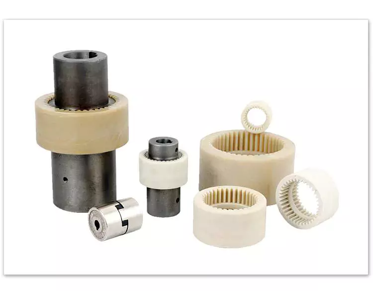
    Gear Coupling Nylon Flexible Torsionally Rigid Stainless Steel Transmission Parts High Quality Good Price Shaft High Precision Dynamic Balance Gear Coupling

    Applications of Spline Couplings

    A spline coupling is a highly effective means of connecting 2 or more components. These types of couplings are very efficient, as they combine linear motion with rotation, and their efficiency makes them a desirable choice in numerous applications. Read on to learn more about the main characteristics and applications of spline couplings. You will also be able to determine the predicted operation and wear. You can easily design your own couplings by following the steps outlined below.
    splineshaft

    Optimal design

    The spline coupling plays an important role in transmitting torque. It consists of a hub and a shaft with splines that are in surface contact without relative motion. Because they are connected, their angular velocity is the same. The splines can be designed with any profile that minimizes friction. Because they are in contact with each other, the load is not evenly distributed, concentrating on a small area, which can deform the hub surface.
    Optimal spline coupling design takes into account several factors, including weight, material characteristics, and performance requirements. In the aeronautics industry, weight is an important design factor. S.A.E. and ANSI tables do not account for weight when calculating the performance requirements of spline couplings. Another critical factor is space. Spline couplings may need to fit in tight spaces, or they may be subject to other configuration constraints.
    Optimal design of spline couplers may be characterized by an odd number of teeth. However, this is not always the case. If the external spline’s outer diameter exceeds a certain threshold, the optimal spline coupling model may not be an optimal choice for this application. To optimize a spline coupling for a specific application, the user may need to consider the sizing method that is most appropriate for their application.
    Once a design is generated, the next step is to test the resulting spline coupling. The system must check for any design constraints and validate that it can be produced using modern manufacturing techniques. The resulting spline coupling model is then exported to an optimisation tool for further analysis. The method enables a designer to easily manipulate the design of a spline coupling and reduce its weight.
    The spline coupling model 20 includes the major structural features of a spline coupling. A product model software program 10 stores default values for each of the spline coupling’s specifications. The resulting spline model is then calculated in accordance with the algorithm used in the present invention. The software allows the designer to enter the spline coupling’s radii, thickness, and orientation.
    splineshaft

    Characteristics

    An important aspect of aero-engine splines is the load distribution among the teeth. The researchers have performed experimental tests and have analyzed the effect of lubrication conditions on the coupling behavior. Then, they devised a theoretical model using a Ruiz parameter to simulate the actual working conditions of spline couplings. This model explains the wear damage caused by the spline couplings by considering the influence of friction, misalignment, and other conditions that are relevant to the splines’ performance.
    In order to design a spline coupling, the user first inputs the design criteria for sizing load carrying sections, including the external spline 40 of the spline coupling model 30. Then, the user specifies torque margin performance requirement specifications, such as the yield limit, plastic buckling, and creep buckling. The software program then automatically calculates the size and configuration of the load carrying sections and the shaft. These specifications are then entered into the model software program 10 as specification values.
    Various spline coupling configuration specifications are input on the GUI screen 80. The software program 10 then generates a spline coupling model by storing default values for the various specifications. The user then can manipulate the spline coupling model by modifying its various specifications. The final result will be a computer-aided design that enables designers to optimize spline couplings based on their performance and design specifications.
    The spline coupling model software program continually evaluates the validity of spline coupling models for a particular application. For example, if a user enters a data value signal corresponding to a parameter signal, the software compares the value of the signal entered to the corresponding value in the knowledge base. If the values are outside the specifications, a warning message is displayed. Once this comparison is completed, the spline coupling model software program outputs a report with the results.
    Various spline coupling design factors include weight, material properties, and performance requirements. Weight is 1 of the most important design factors, particularly in the aeronautics field. ANSI and S.A.E. tables do not consider these factors when calculating the load characteristics of spline couplings. Other design requirements may also restrict the configuration of a spline coupling.

    Applications

    Spline couplings are a type of mechanical joint that connects 2 rotating shafts. Its 2 parts engage teeth that transfer load. Although splines are commonly over-dimensioned, they are still prone to fatigue and static behavior. These properties also make them prone to wear and tear. Therefore, proper design and selection are vital to minimize wear and tear on splines. There are many applications of spline couplings.
    A key design is based on the size of the shaft being joined. This allows for the proper spacing of the keys. A novel method of hobbing allows for the formation of tapered bases without interference, and the root of the keys is concentric with the axis. These features enable for high production rates. Various applications of spline couplings can be found in various industries. To learn more, read on.
    FE based methodology can predict the wear rate of spline couplings by including the evolution of the coefficient of friction. This method can predict fretting wear from simple round-on-flat geometry, and has been calibrated with experimental data. The predicted wear rate is reasonable compared to the experimental data. Friction evolution in spline couplings depends on the spline geometry. It is also crucial to consider the lubrication condition of the splines.
    Using a spline coupling reduces backlash and ensures proper alignment of mated components. The shaft’s splined tooth form transfers rotation from the splined shaft to the internal splined member, which may be a gear or other rotary device. A spline coupling’s root strength and torque requirements determine the type of spline coupling that should be used.
    The spline root is usually flat and has a crown on 1 side. The crowned spline has a symmetrical crown at the centerline of the face-width of the spline. As the spline length decreases toward the ends, the teeth are becoming thinner. The tooth diameter is measured in pitch. This means that the male spline has a flat root and a crowned spline.
    splineshaft

    Predictability

    Spindle couplings are used in rotating machinery to connect 2 shafts. They are composed of 2 parts with teeth that engage each other and transfer load. Spline couplings are commonly over-dimensioned and are prone to static and fatigue behavior. Wear phenomena are also a common problem with splines. To address these issues, it is essential to understand the behavior and predictability of these couplings.
    Dynamic behavior of spline-rotor couplings is often unclear, particularly if the system is not integrated with the rotor. For example, when a misalignment is not present, the main response frequency is 1 X-rotating speed. As the misalignment increases, the system starts to vibrate in complex ways. Furthermore, as the shaft orbits depart from the origin, the magnitudes of all the frequencies increase. Thus, research results are useful in determining proper design and troubleshooting of rotor systems.
    The model of misaligned spline couplings can be obtained by analyzing the stress-compression relationships between 2 spline pairs. The meshing force model of splines is a function of the system mass, transmitting torque, and dynamic vibration displacement. This model holds when the dynamic vibration displacement is small. Besides, the CZPT stepping integration method is stable and has high efficiency.
    The slip distributions are a function of the state of lubrication, coefficient of friction, and loading cycles. The predicted wear depths are well within the range of measured values. These predictions are based on the slip distributions. The methodology predicts increased wear under lightly lubricated conditions, but not under added lubrication. The lubrication condition and coefficient of friction are the key factors determining the wear behavior of splines.

    China wholesaler Gear CZPT Nylon Flexible Torsionally Rigid Stainless Steel Transmission Parts High Quality Good Price Shaft High Precision Dynamic Balance Gear CZPT     with high qualityChina wholesaler Gear CZPT Nylon Flexible Torsionally Rigid Stainless Steel Transmission Parts High Quality Good Price Shaft High Precision Dynamic Balance Gear CZPT     with high quality

    China OEM Gear CZPT Nylon Flexible Torsionally Rigid Stainless Steel Transmission Parts High Quality Good Price Shaft High Precision Dynamic Balance Gear CZPT wholesaler

    Product Description

    Gear Coupling Nylon Flexible Torsionally Rigid Stainless Steel Transmission Parts High Quality Good Price Shaft High Precision Dynamic Balance Gear Coupling

    Stiffness and Torsional Vibration of Spline-Couplings

    In this paper, we describe some basic characteristics of spline-coupling and examine its torsional vibration behavior. We also explore the effect of spline misalignment on rotor-spline coupling. These results will assist in the design of improved spline-coupling systems for various applications. The results are presented in Table 1.
    splineshaft

    Stiffness of spline-coupling

    The stiffness of a spline-coupling is a function of the meshing force between the splines in a rotor-spline coupling system and the static vibration displacement. The meshing force depends on the coupling parameters such as the transmitting torque and the spline thickness. It increases nonlinearly with the spline thickness.
    A simplified spline-coupling model can be used to evaluate the load distribution of splines under vibration and transient loads. The axle spline sleeve is displaced a z-direction and a resistance moment T is applied to the outer face of the sleeve. This simple model can satisfy a wide range of engineering requirements but may suffer from complex loading conditions. Its asymmetric clearance may affect its engagement behavior and stress distribution patterns.
    The results of the simulations show that the maximum vibration acceleration in both Figures 10 and 22 was 3.03 g/s. This results indicate that a misalignment in the circumferential direction increases the instantaneous impact. Asymmetry in the coupling geometry is also found in the meshing. The right-side spline’s teeth mesh tightly while those on the left side are misaligned.
    Considering the spline-coupling geometry, a semi-analytical model is used to compute stiffness. This model is a simplified form of a classical spline-coupling model, with submatrices defining the shape and stiffness of the joint. As the design clearance is a known value, the stiffness of a spline-coupling system can be analyzed using the same formula.
    The results of the simulations also show that the spline-coupling system can be modeled using MASTA, a high-level commercial CAE tool for transmission analysis. In this case, the spline segments were modeled as a series of spline segments with variable stiffness, which was calculated based on the initial gap between spline teeth. Then, the spline segments were modelled as a series of splines of increasing stiffness, accounting for different manufacturing variations. The resulting analysis of the spline-coupling geometry is compared to those of the finite-element approach.
    Despite the high stiffness of a spline-coupling system, the contact status of the contact surfaces often changes. In addition, spline coupling affects the lateral vibration and deformation of the rotor. However, stiffness nonlinearity is not well studied in splined rotors because of the lack of a fully analytical model.
    splineshaft

    Characteristics of spline-coupling

    The study of spline-coupling involves a number of design factors. These include weight, materials, and performance requirements. Weight is particularly important in the aeronautics field. Weight is often an issue for design engineers because materials have varying dimensional stability, weight, and durability. Additionally, space constraints and other configuration restrictions may require the use of spline-couplings in certain applications.
    The main parameters to consider for any spline-coupling design are the maximum principal stress, the maldistribution factor, and the maximum tooth-bearing stress. The magnitude of each of these parameters must be smaller than or equal to the external spline diameter, in order to provide stability. The outer diameter of the spline must be at least 4 inches larger than the inner diameter of the spline.
    Once the physical design is validated, the spline coupling knowledge base is created. This model is pre-programmed and stores the design parameter signals, including performance and manufacturing constraints. It then compares the parameter values to the design rule signals, and constructs a geometric representation of the spline coupling. A visual model is created from the input signals, and can be manipulated by changing different parameters and specifications.
    The stiffness of a spline joint is another important parameter for determining the spline-coupling stiffness. The stiffness distribution of the spline joint affects the rotor’s lateral vibration and deformation. A finite element method is a useful technique for obtaining lateral stiffness of spline joints. This method involves many mesh refinements and requires a high computational cost.
    The diameter of the spline-coupling must be large enough to transmit the torque. A spline with a larger diameter may have greater torque-transmitting capacity because it has a smaller circumference. However, the larger diameter of a spline is thinner than the shaft, and the latter may be more suitable if the torque is spread over a greater number of teeth.
    Spline-couplings are classified according to their tooth profile along the axial and radial directions. The radial and axial tooth profiles affect the component’s behavior and wear damage. Splines with a crowned tooth profile are prone to angular misalignment. Typically, these spline-couplings are oversized to ensure durability and safety.

    Stiffness of spline-coupling in torsional vibration analysis

    This article presents a general framework for the study of torsional vibration caused by the stiffness of spline-couplings in aero-engines. It is based on a previous study on spline-couplings. It is characterized by the following 3 factors: bending stiffness, total flexibility, and tangential stiffness. The first criterion is the equivalent diameter of external and internal splines. Both the spline-coupling stiffness and the displacement of splines are evaluated by using the derivative of the total flexibility.
    The stiffness of a spline joint can vary based on the distribution of load along the spline. Variables affecting the stiffness of spline joints include the torque level, tooth indexing errors, and misalignment. To explore the effects of these variables, an analytical formula is developed. The method is applicable for various kinds of spline joints, such as splines with multiple components.
    Despite the difficulty of calculating spline-coupling stiffness, it is possible to model the contact between the teeth of the shaft and the hub using an analytical approach. This approach helps in determining key magnitudes of coupling operation such as contact peak pressures, reaction moments, and angular momentum. This approach allows for accurate results for spline-couplings and is suitable for both torsional vibration and structural vibration analysis.
    The stiffness of spline-coupling is commonly assumed to be rigid in dynamic models. However, various dynamic phenomena associated with spline joints must be captured in high-fidelity drivetrain models. To accomplish this, a general analytical stiffness formulation is proposed based on a semi-analytical spline load distribution model. The resulting stiffness matrix contains radial and tilting stiffness values as well as torsional stiffness. The analysis is further simplified with the blockwise inversion method.
    It is essential to consider the torsional vibration of a power transmission system before selecting the coupling. An accurate analysis of torsional vibration is crucial for coupling safety. This article also discusses case studies of spline shaft wear and torsionally-induced failures. The discussion will conclude with the development of a robust and efficient method to simulate these problems in real-life scenarios.
    splineshaft

    Effect of spline misalignment on rotor-spline coupling

    In this study, the effect of spline misalignment in rotor-spline coupling is investigated. The stability boundary and mechanism of rotor instability are analyzed. We find that the meshing force of a misaligned spline coupling increases nonlinearly with spline thickness. The results demonstrate that the misalignment is responsible for the instability of the rotor-spline coupling system.
    An intentional spline misalignment is introduced to achieve an interference fit and zero backlash condition. This leads to uneven load distribution among the spline teeth. A further spline misalignment of 50um can result in rotor-spline coupling failure. The maximum tensile root stress shifted to the left under this condition.
    Positive spline misalignment increases the gear mesh misalignment. Conversely, negative spline misalignment has no effect. The right-handed spline misalignment is opposite to the helix hand. The high contact area is moved from the center to the left side. In both cases, gear mesh is misaligned due to deflection and tilting of the gear under load.
    This variation of the tooth surface is measured as the change in clearance in the transverse plain. The radial and axial clearance values are the same, while the difference between the 2 is less. In addition to the frictional force, the axial clearance of the splines is the same, which increases the gear mesh misalignment. Hence, the same procedure can be used to determine the frictional force of a rotor-spline coupling.
    Gear mesh misalignment influences spline-rotor coupling performance. This misalignment changes the distribution of the gear mesh and alters contact and bending stresses. Therefore, it is essential to understand the effects of misalignment in spline couplings. Using a simplified system of helical gear pair, Hong et al. examined the load distribution along the tooth interface of the spline. This misalignment caused the flank contact pattern to change. The misaligned teeth exhibited deflection under load and developed a tilting moment on the gear.
    The effect of spline misalignment in rotor-spline couplings is minimized by using a mechanism that reduces backlash. The mechanism comprises cooperably splined male and female members. One member is formed by 2 coaxially aligned splined segments with end surfaces shaped to engage in sliding relationship. The connecting device applies axial loads to these segments, causing them to rotate relative to 1 another.

    China OEM Gear CZPT Nylon Flexible Torsionally Rigid Stainless Steel Transmission Parts High Quality Good Price Shaft High Precision Dynamic Balance Gear CZPT     wholesaler China OEM Gear CZPT Nylon Flexible Torsionally Rigid Stainless Steel Transmission Parts High Quality Good Price Shaft High Precision Dynamic Balance Gear CZPT     wholesaler

    China Good quality Flexible Gear CZPT Nylon Torsionally Rigid Stainless Steel Transmission Parts High Quality Good Price Shaft High Precision Dynamic Balance Gear CZPT with Great quality

    Product Description

    Flexible Gear Coupling Nylon Torsionally Rigid Stainless Steel Transmission Parts High Quality Good Price Shaft High Precision Dynamic Balance Gear Coupling


    The Different Types of Splines in a Splined Shaft

    A splined shaft is a machine component with internal and external splines. The splines are formed in 4 different ways: Involute, Parallel, Serrated, and Ball. You can learn more about each type of spline in this article. When choosing a splined shaft, be sure to choose the right 1 for your application. Read on to learn about the different types of splines and how they affect the shaft’s performance.
    splineshaft

    Involute splines

    Involute splines in a splined shaft are used to secure and extend mechanical assemblies. They are smooth, inwardly curving grooves that resist separation during operation. A shaft with involute splines is often longer than the shaft itself. This feature allows for more axial movement. This is beneficial for many applications, especially in a gearbox.
    The involute spline is a shaped spline, similar to a parallel spline. It is angled and consists of teeth that create a spiral pattern that enables linear and rotatory motion. It is distinguished from other splines by the serrations on its flanks. It also has a flat top. It is a good option for couplers and other applications where angular movement is necessary.
    Involute splines are also called involute teeth because of their shape. They are flat on the top and curved on the sides. These teeth can be either internal or external. As a result, involute splines provide greater surface contact, which helps reduce stress and fatigue. Regardless of the shape, involute splines are generally easy to machine and fit.
    Involute splines are a type of splines that are used in splined shafts. These splines have different names, depending on their diameters. An example set of designations is for a 32-tooth male spline, a 2,500-tooth module, and a 30 degree pressure angle. An example of a female spline, a fillet root spline, is used to describe the diameter of the splined shaft.
    The effective tooth thickness of splines is dependent on the number of keyways and the type of spline. Involute splines in splined shafts should be designed to engage 25 to 50 percent of the spline teeth during the coupling. Involute splines should be able to withstand the load without cracking.

    Parallel splines

    Parallel splines are formed on a splined shaft by putting 1 or more teeth into another. The male spline is positioned at the center of the female spline. The teeth of the male spline are also parallel to the shaft axis, but a common misalignment causes the splines to roll and tilt. This is common in many industrial applications, and there are a number of ways to improve the performance of splines.
    Typically, parallel splines are used to reduce friction in a rotating part. The splines on a splined shaft are narrower on the end face than the interior, which makes them more prone to wear. This type of spline is used in a variety of industries, such as machinery, and it also allows for greater efficiency when transmitting torque.
    Involute splines on a splined shaft are the most common. They have equally spaced teeth, and are therefore less likely to crack due to fatigue. They also tend to be easy to cut and fit. However, they are not the best type of spline. It is important to understand the difference between parallel and involute splines before deciding on which spline to use.
    The difference between splined and involute splines is the size of the grooves. Involute splines are generally larger than parallel splines. These types of splines provide more torque to the gear teeth and reduce stress during operation. They are also more durable and have a longer life span. And because they are used on farm machinery, they are essential in this type of application.
    splineshaft

    Serrated splines

    A Serrated Splined Shaft has several advantages. This type of shaft is highly adjustable. Its large number of teeth allows large torques, and its shorter tooth width allows for greater adjustment. These features make this type of shaft an ideal choice for applications where accuracy is critical. Listed below are some of the benefits of this type of shaft. These benefits are just a few of the advantages. Learn more about this type of shaft.
    The process of hobbing is inexpensive and highly accurate. It is useful for external spline shafts, but is not suitable for internal splines. This type of process forms synchronized shapes on the shaft, reducing the manufacturing cycle and stabilizing the relative phase between spline and thread. It uses a grinding wheel to shape the shaft. CZPT Manufacturing has a large inventory of Serrated Splined Shafts.
    The teeth of a Serrated Splined Shaft are designed to engage with the hub over the entire circumference of the shaft. The teeth of the shaft are spaced uniformly around the spline, creating a multiple-tooth point of contact over the entire length of the shaft. The results of these analyses are usually satisfactory. But there are some limitations. To begin with, the splines of the Serrated Splined Shaft should be chosen carefully. If the application requires large-scale analysis, it may be necessary to modify the design.
    The splines of the Serrated Splined Shaft are also used for other purposes. They can be used to transmit torque to another device. They also act as an anti-rotational device and function as a linear guide. Both the design and the type of splines determine the function of the Splined Shaft. In the automobile industry, they are used in vehicles, aerospace, earth-moving machinery, and many other industries.

    Ball splines

    The invention relates to a ball-spinned shaft. The shaft comprises a plurality of balls that are arranged in a series and are operatively coupled to a load path section. The balls are capable of rolling endlessly along the path. This invention also relates to a ball bearing. Here, a ball bearing is 1 of the many types of gears. The following discussion describes the features of a ball bearing.
    A ball-splined shaft assembly comprises a shaft with at least 1 ball-spline groove and a plurality of circumferential step grooves. The shaft is held in a first holding means that extends longitudinally and is rotatably held by a second holding means. Both the shaft and the first holding means are driven relative to 1 another by a first driving means. It is possible to manufacture a ball-splined shaft in a variety of ways.
    A ball-splined shaft features a nut with recirculating balls. The ball-splined nut rides in these grooves to provide linear motion while preventing rotation. A splined shaft with a nut that has recirculating balls can also provide rotary motion. A ball splined shaft also has higher load capacities than a ball bushing. For these reasons, ball splines are an excellent choice for many applications.
    In this invention, a pair of ball-spinned shafts are housed in a box under a carrier device 40. Each of the 2 shafts extends along a longitudinal line of arm 50. One end of each shaft is supported rotatably by a slide block 56. The slide block also has a support arm 58 that supports the center arm 50 in a cantilever fashion.
    splineshaft

    Sector no-go gage

    A no-go gauge is a tool that checks the splined shaft for oversize. It is an effective way to determine the oversize condition of a splined shaft without removing the shaft. It measures external splines and serrations. The no-go gage is available in sizes ranging from 19mm to 130mm with a 25mm profile length.
    The sector no-go gage has 2 groups of diametrally opposed teeth. The space between them is manufactured to a maximum space width and the tooth thickness must be within a predetermined tolerance. This gage would be out of tolerance if the splines were measured with a pin. The dimensions of this splined shaft can be found in the respective ANSI or DIN standards.
    The go-no-go gage is useful for final inspection of thread pitch diameter. It is also useful for splined shafts and threaded nuts. The thread of a screw must match the contour of the go-no-go gage head to avoid a no-go condition. There is no substitute for a quality machine. It is an essential tool for any splined shaft and fastener manufacturer.
    The NO-GO gage can detect changes in tooth thickness. It can be calibrated under ISO17025 standards and has many advantages over a non-go gage. It also gives a visual reference of the thickness of a splined shaft. When the teeth match, the shaft is considered ready for installation. It is a critical process. In some cases, it is impossible to determine the precise length of the shaft spline.
    The 45-degree pressure angle is most commonly used for axles and torque-delivering members. This pressure angle is the most economical in terms of tool life, but the splines will not roll neatly like a 30 degree angle. The 45-degree spline is more likely to fall off larger than the other two. Oftentimes, it will also have a crowned look. The 37.5 degree pressure angle is a compromise between the other 2 pressure angles. It is often used when the splined shaft material is harder than usual.

    China Good quality Flexible Gear CZPT Nylon Torsionally Rigid Stainless Steel Transmission Parts High Quality Good Price Shaft High Precision Dynamic Balance Gear CZPT     with Great qualityChina Good quality Flexible Gear CZPT Nylon Torsionally Rigid Stainless Steel Transmission Parts High Quality Good Price Shaft High Precision Dynamic Balance Gear CZPT     with Great quality